|
|
|
|
                                   
|
My first Tesla Coil 'discovery' My first proper Tesla Coil (circa 1975)
Tesla c
What is a Tesla coil?
2003
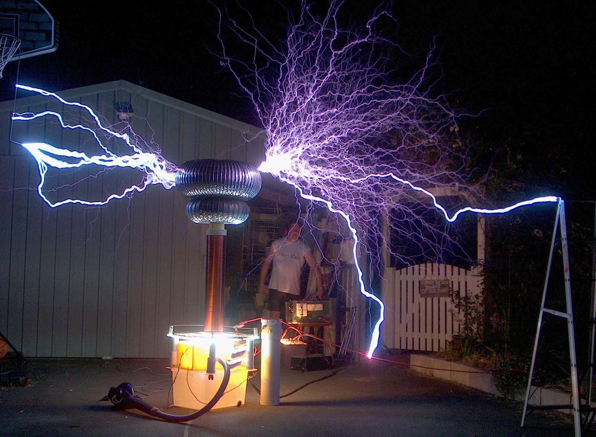
From the Tesla coil sparks page. A Tesla coil such as this one with sparks of 8 feet equates to about 500,000 Volts. It is very hard to measure this voltage directly. See calculations of voltage in Tesla coil 6 inch. The largest spark that I am aware of at 325 ft was from a 5 MV Marx generator, not a Tesla coil. Interestingly, real lightning is only estimated to be 10 - 120 MV . Lightning length appears to be determined by cosmic ray shower activity and is vastly extended in length due to relativistic electrons initiated by the cosmic shower. A simplified circuit diagram of my latest coil is shown below and also includes various filter circuitry and safety spark gaps to prevent the very high voltages from wreaking havoc with the lower voltage side. It includes 4 microwave oven transformers (MOT's) driven by a variac. These supply about 8 kV to the primary coil, capacitor and spark gap. This circuit is resonant at about 100 kHz and drives the secondary coil and toroid which are resonant at the same frequency.
My first Tesla Coil
'discovery'
1972
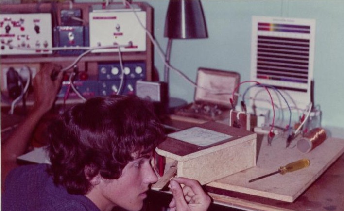
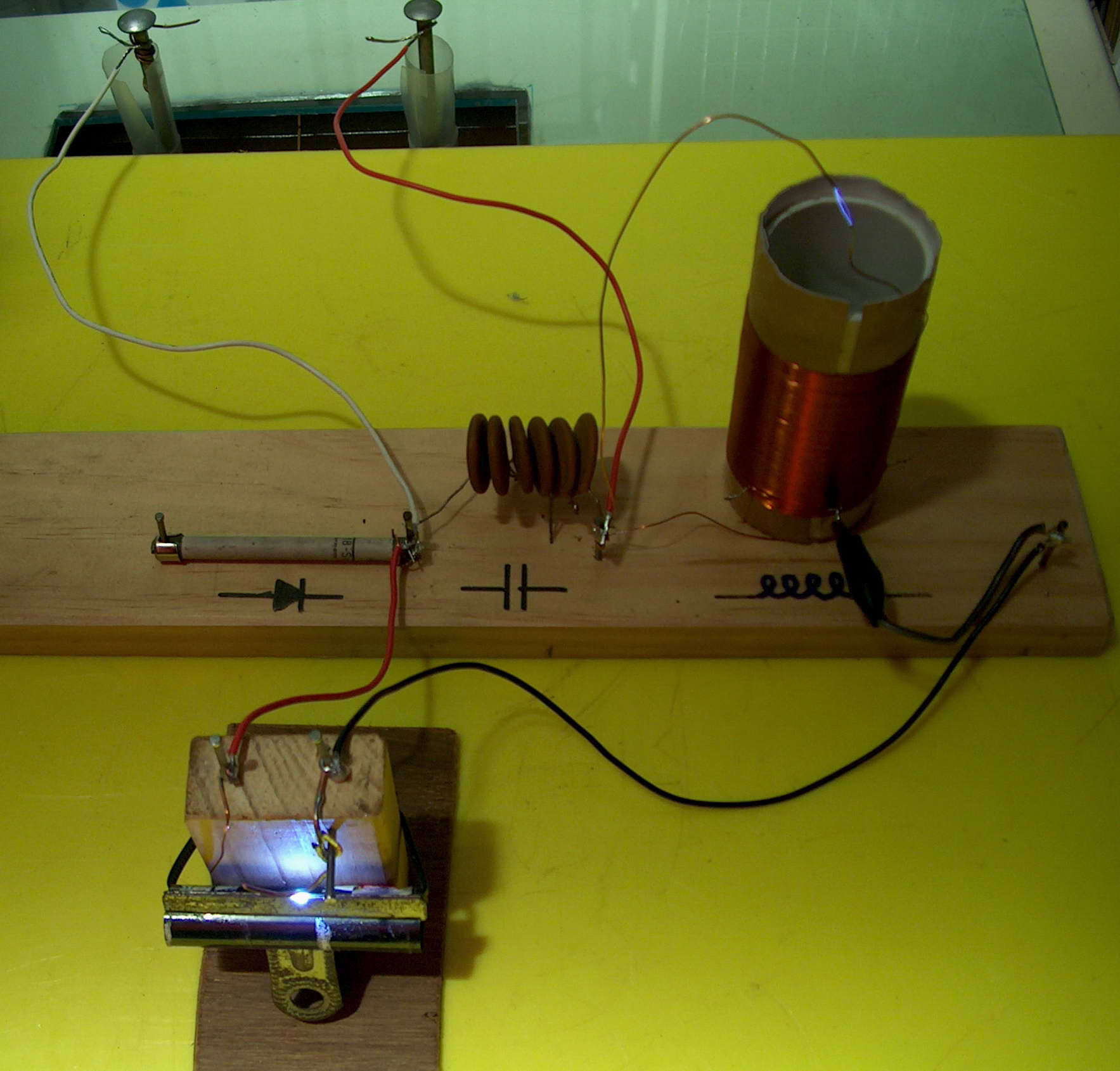
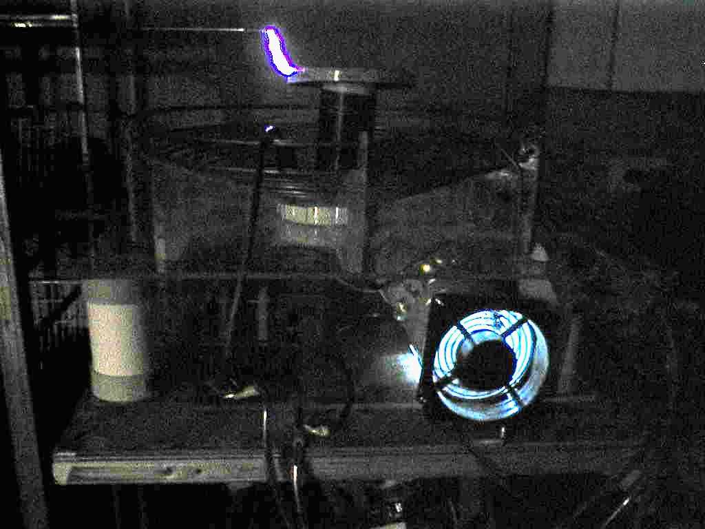
The left photo shows the spark spectroscopy
setup in use (but not in operation as a Tesla coil). The right
photo
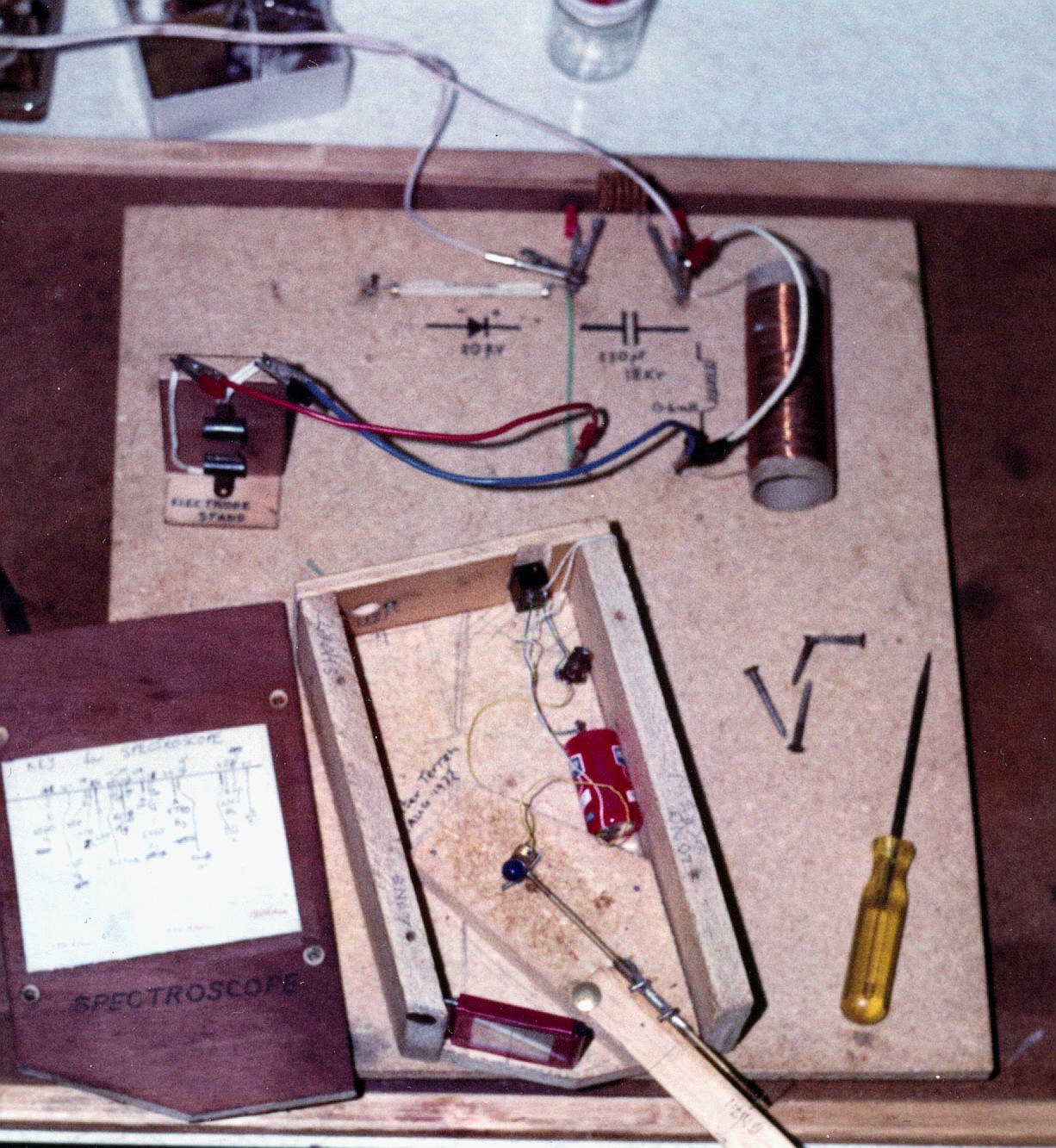
shows the original high voltage setup with the spectroscope shown open
and the HV diode, air cored coil and cap made of 6 x 0.0033 uF 3 kV
ceramics in series to give 550 pF. The spark gap with clips to hold
the metal being examined spectroscopically is also shown.
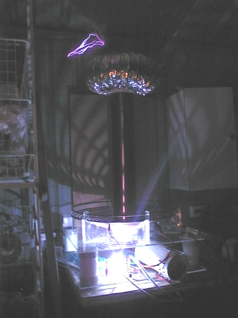
Above shows a reconstruction which took about an hour to make in May
2005. It uses the same size cardboard former as the old one 45x100 mm
which had to be reinforced with PVC. (Toilet rolls are not as strong
in 2005 as 1972) The wire gauge is 0.40 mm (prev 0.6 mm) and is wound
to 130 turns with multiple taps between 10 and 20 turns. The caps were
6 x 0.01 3 kV = 1600 pF (prev 550 pF) and power supply was my SIDAC
driven twin ignition coil setup. Spark gap was about 2mm as anything
higher gave racing arcs! My first proper Tesla Coil (circa 1975)
I later developed this idea with an old transformer (above) from a dump which in retrospect was an old unpotted NST (neon sign transformer). I used a single static gap with a 12 inch ferrite cored coil of 11 primary and 100 turns secondary giving 2 inch sparks with 26 small ceramic capacitors with 2 strings of 13 x 10 nF at 2.5 kV each. It ran nicely for about 20 years! Years after I made it I heard that Tesla had beaten me to that discovery by quite a few years! This photo is a mock up with most of the original parts. Developing my 4 inch coil 2003
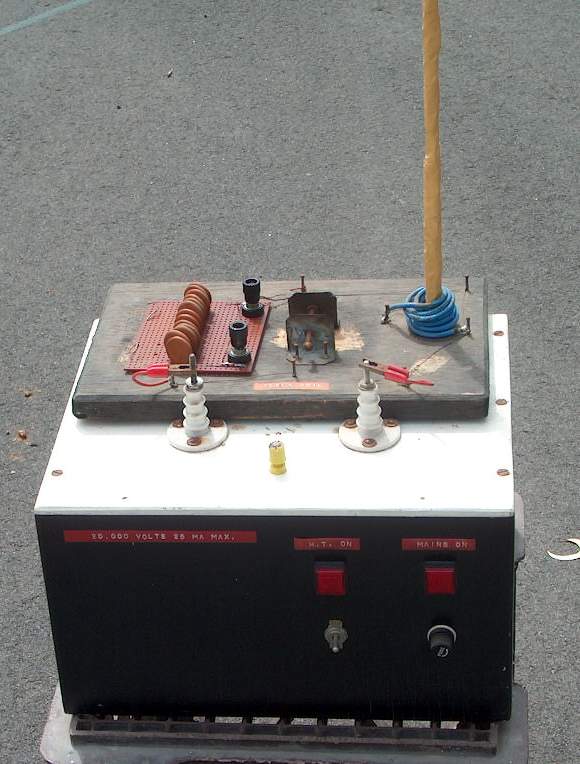
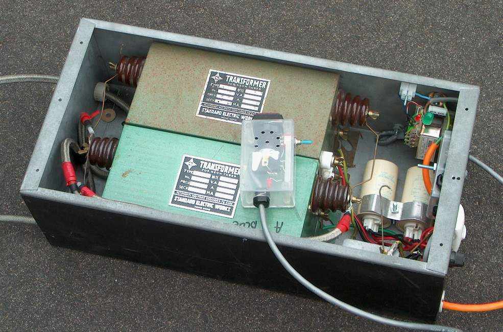
This is my neat 2001 dual NST supply (above), now has half of one of the NST's defunct having overstressed it on my ARSG (asynchronous rotary spark gap). It used two old NST's bought for A$40 from a local neon place and rated at 12 kV 30 mA each. It uses two power factor correction capacitors of 15 uF each. I used a remote power switch driving a relay.
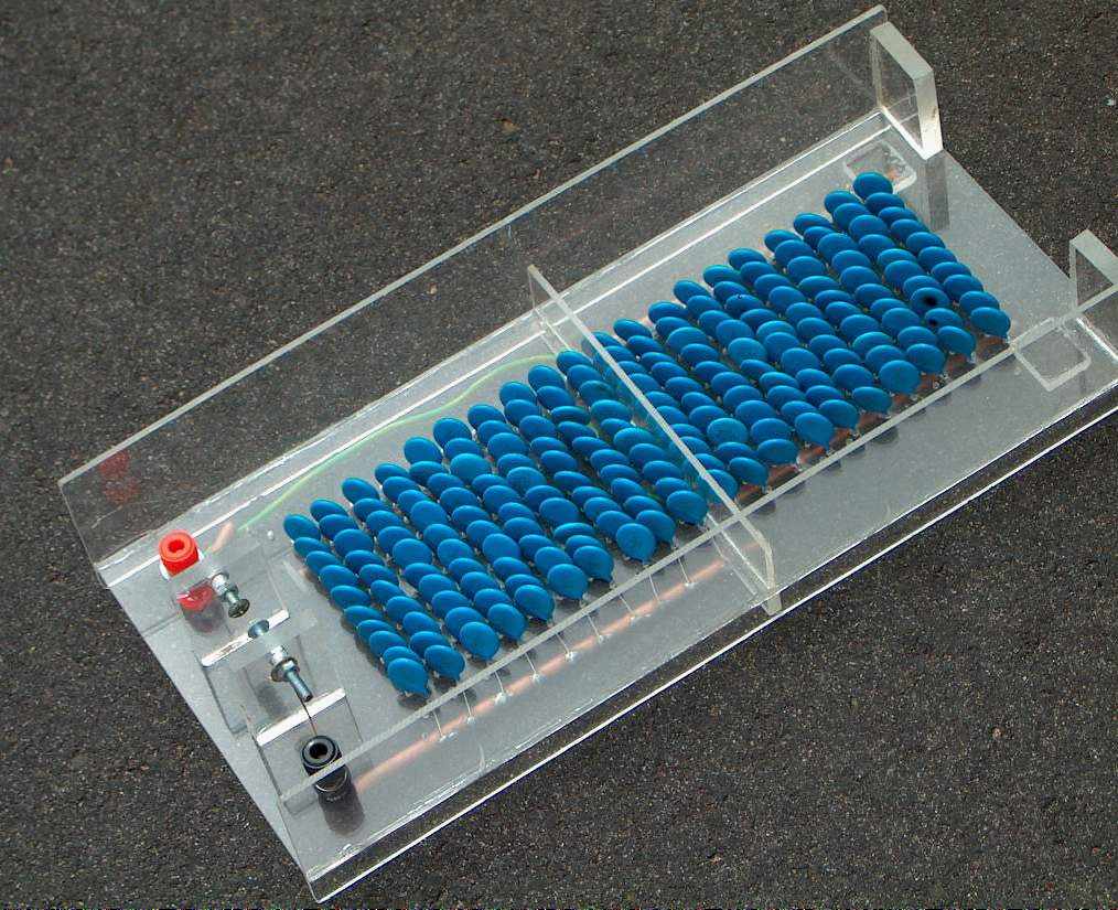
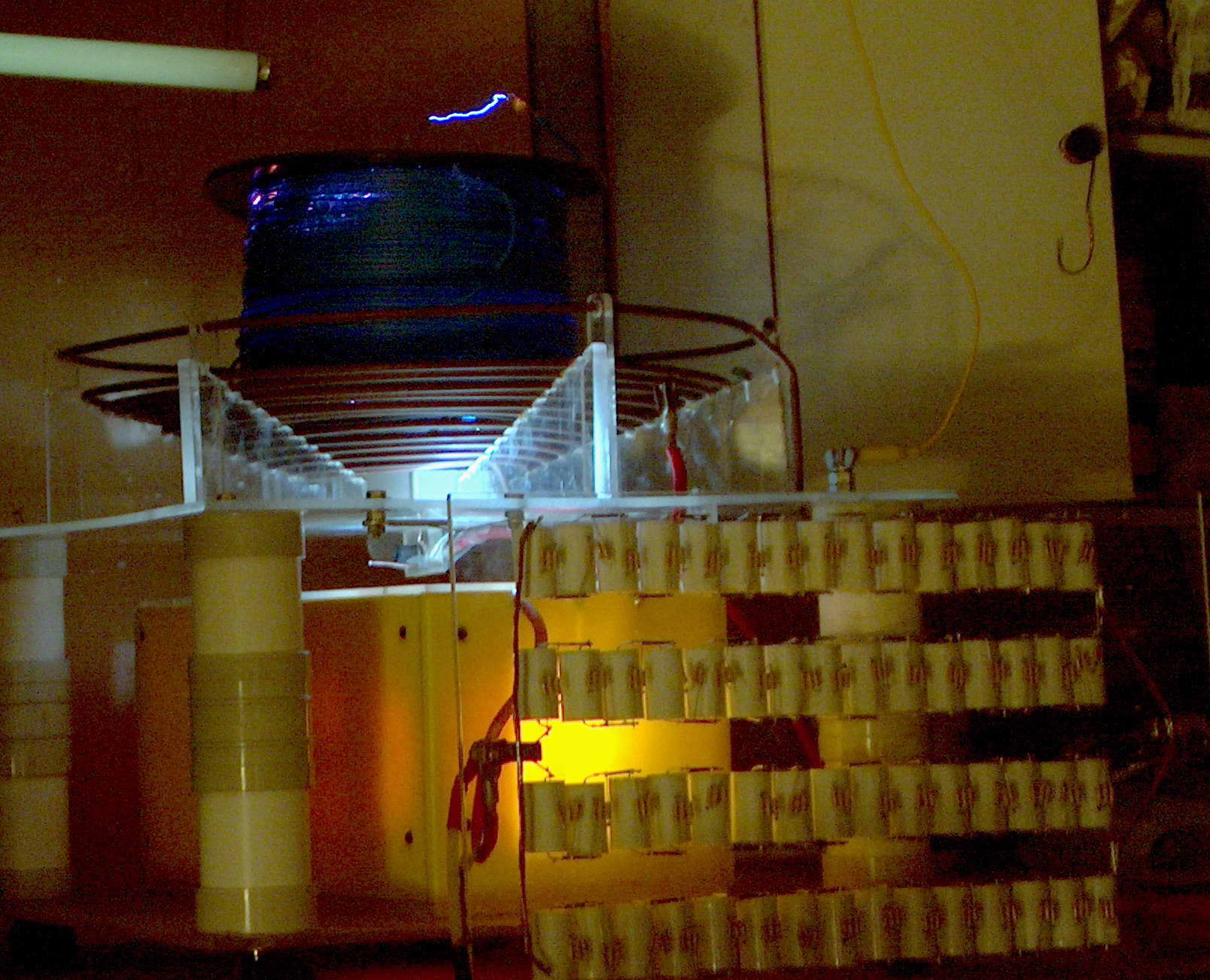
This is how NOT to make 20 nF 30 kV capacitors. I used 200 x 10 nF (= 0.01 uF) 3 kV ceramics. Even wired as 10 nF 60 kV, I would blow a capacitor every 30 seconds or so. They appeared to be substantially less well rated than the long lasting ceramics in my first TC. There were no equalizing resistors in either setup. It was later sawn in half for a voltage multiplier shown later.
The sparks grew bigger with successive improvements up to about 20 inches. Having gained a lot of experience and having read widely on the internet increased my desire for more performance. Time to move up: 'bigger is better'. (Remember this was 2003). Head off to see the later 4 inch, 6 inch and 18 inch coils from the menu at the top of the page.
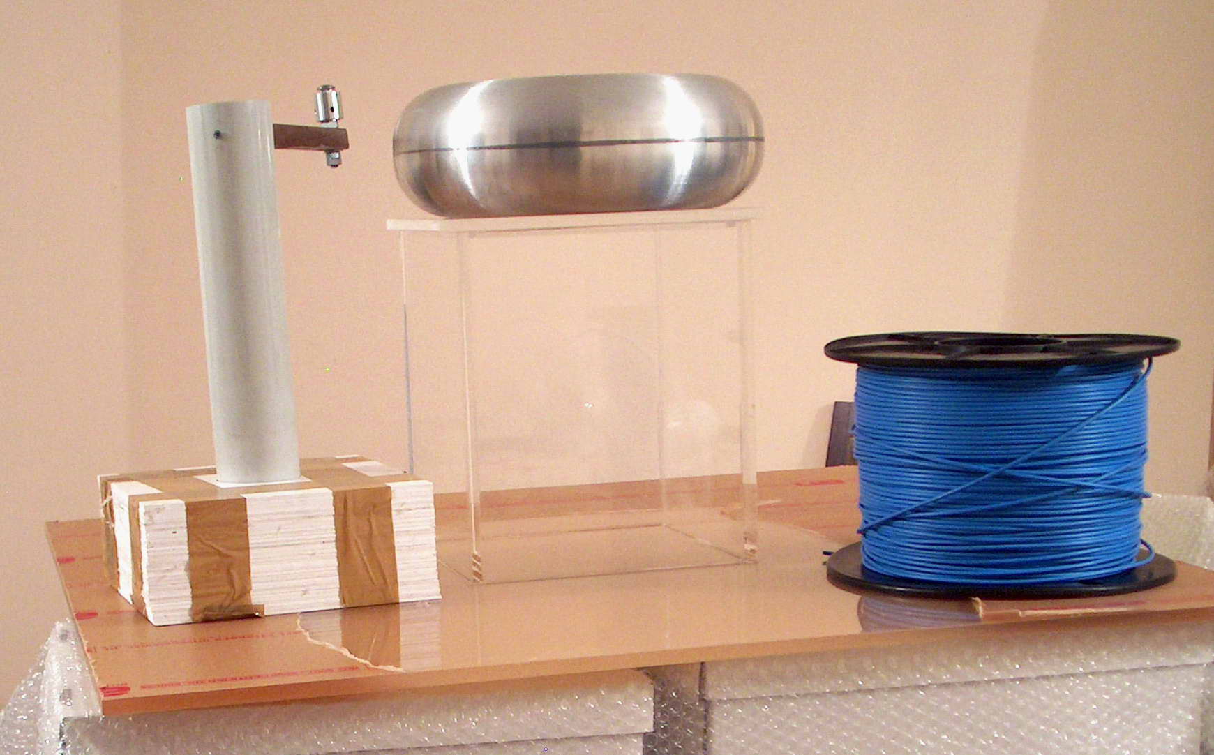
Multilayer Tesla coil
2005
My plan is to optimize this to get the highest possible spark length to
coil length ratio.
I now have the 60 square spacers and the square housing to contain these
under oil, fixed to a large square base. The wire is ready and a toroid
is available. Now just have to undertake the complicated task of winding
the multiple pancake coils.
|
This page was last updated April 10, 2011